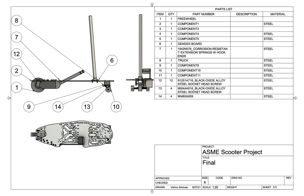
Overview:
For Summer 2021, the Purdue chapter of the American Society of Mechanical Engineers (ASME) hosted a design contest sponsored by Autodesk. The challenge? Design a vehicle that could function as either a skateboard or a scooter using Fusion 360. The winners would win cash prizes and the best design would then be actually manufactured by the Purdue Polytechnic Institute.
A partner and I spent 3 months working on this project remotely. Our design won the 3rd place prize and 500 dollars.
Ideation
When I first heard about this competition, my mind immediately went to my experience riding, maintaining, and rebuilding bicycles. If we could find a way to bring the convenience and speed of a bicycle to the frame of a hybrid skateboard/scooter, I thought we would be able to design a genuinely useful vehicle. The huge rise in demand for electric scooters in the past few years was further proof that this idea, if successfully implemented, would be a winner.
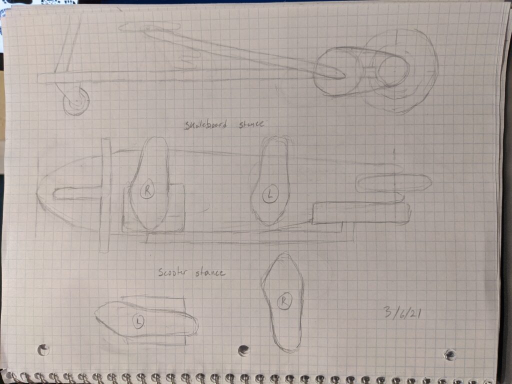
First full ideation sketch, outlining basic form and riding position
Design Part I: Gears
The most complicated part of this design concept was the gearbox system. There would need to be some way to turn the torque provided by the rider into speed if we wanted to make our design the high-speed commuter we envisioned.

Some of the calculations done to determine our overall gear ratio
After Looking into many different ways to achieve our desired gear ratio (planetary gears, sprocket + chain, compound planetary gears), we decided to just design a linear gear set (like the one shown below) because we knew that it would be manufacturable for polytechnic students.
Considering the manufacturing capabilities and limitations that our project would face became a very important priority for us as we designed our product. It also helped us learn about manufacturing tools even though we were still quarantining at home, far from any machine shop.

Early linear gear set design
Design Part II: Freewheel
Our next drive mechanism challenge stemmed from the biggest difference between our pedal mechanism and a traditional bicycle mechanism: we only had one pedal.
This meant that while the pedal had to rotate both towards the ground (when being stepped on) and away from the ground (when released so that it can be stepped on again) even though the rear wheel should only rotate in one direction (forward).
How could this be achieved?
I knew from my experience with bikes that I would have to design a freewheel.
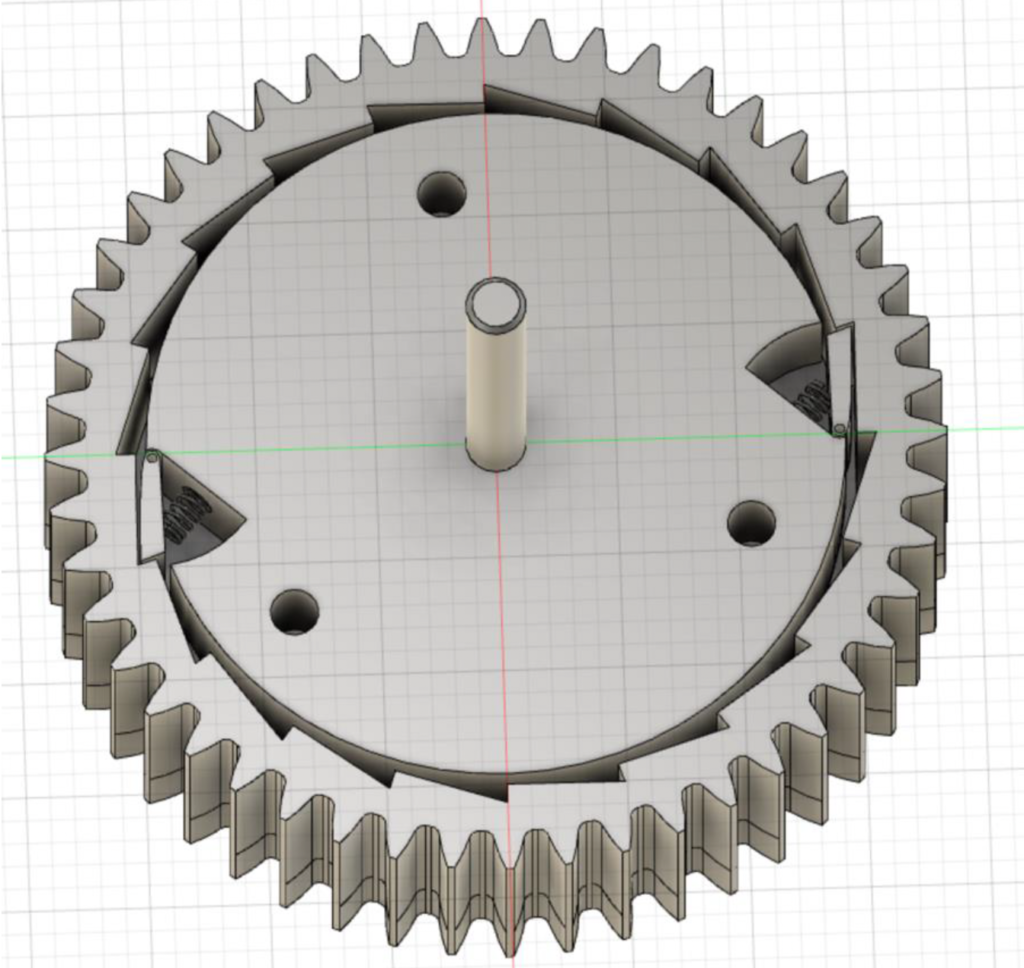
My basic freewheel design
Consists of an inner disk with two spring-loaded pawls and an outer shell

Exploded view of full freewheel assembly
Design Part III: Integration
The first step of putting our final design together was to integrate the parts we already had. We began by combining the freewheel, gear assembly, and a standard scooter wheel with a protective shell that would protect the mechanism and user from each other.
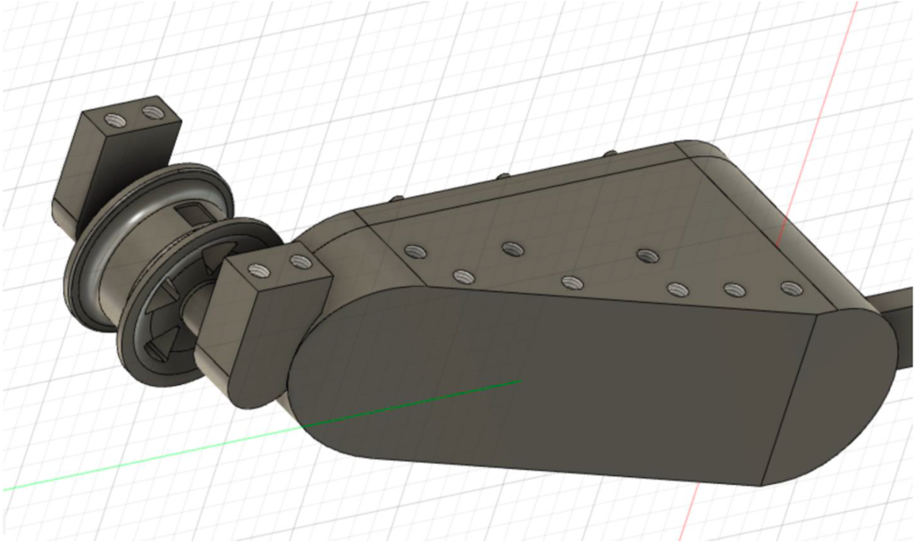
Gear, shell, and wheel assembly

Cross-section view of linear gears and freewheel inside shell
The next step was to design our deck and handle. One of the requirements of the competition was to use Fusion 360’s generative design feature, so we used it to generate a board which was strong enough to withstand a rider, yet that saved as much weight as possible.
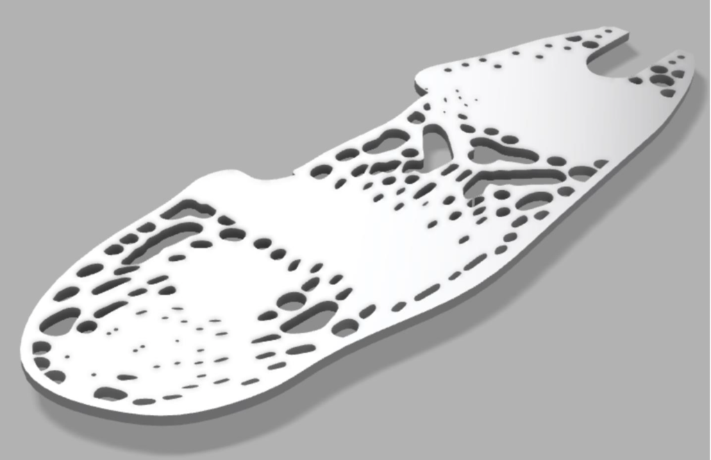
Fusion 360 Generative Design-ed board
We combined these components with a simple handle that could be bolted or unbolted for flexibility and a spring-loaded pedal that would allow for single-pedal propulsion to get our final design:
